The transmitter side of a telemetry system is where the data streams from the sensors are collected and sent over a transmission line for remote storage and processing. This article gives a short overview of some of the theoretical practicalities of how this is done, focusing on the ideas rather than the electronics.
Multiplexing
A typical telemetry setup has more than one sensor, and thus more than one data stream which needs to be transferred simultaneously. This brings us to the topic of multiplexing—techniques for combining multiple signals into one, thereby ‘multiplying’ any given communication link (the term multiplexing is from Latin and translates to ‘multiplication’). Although some channels have special characteristics which can be exploited for multiplexing—like the polarization of electromagnetic waves—all communication links have three aspects in common:

- Time: To the best of our knowledge, no information can be transferred faster than the speed of light in a vacuum. Hence, all communication will be stretched out in time.
- Bandwidth: Conveying information requires something to move, i.e. to change. Although there are no theoretical upper bounds on how quickly something might change, all practical systems built to date have an upper frequency limit, and thus a certain bandwidth (all systems have a lower frequency limit).
- Encoding: Unless the physical quantity being measured is transferred directly (in which case one could argue that what is being done is not telemetry), communication is achieved through the use of an intermediate set of (in principle) arbitrary symbols. This is especially true for digital communication schemes.
Each of these features can be exploited for multiplexing:
- Time-division multiplexing: The different messages are distributed over the time dimension. Pseudo-continuous communication can be achieved by sending only one data point in each time slot. This approach is still used in some telephone systems, and is also popular on scientific sounding rockets.
- Frequency-division multiplexing: All messages are sent concurrently, but distributed over different parts of the frequency spectrum. Although all channels are transmitting simultaneously, this does not mean that the total information speed is higher, as each channel has to make do with its designated bandwidth slot. This approach is used in analogue radio.
- Code-division multiplexing: Normally easier to implement with digital than analogue signals, all messages are sent simultaneously, but using symbols which can always be untangled even though they are transmitted concurrently. If the system only have one transmitter—or if the transmitters are all synchronized—this can be done by using orthogonal vectors to encode the different channels. If the transmitters are not synchronized, it is necessary to use symbols which are statistically uncorrelated rather than orthogonal. This can be done using pseudo-random sequences to encode the different channels (a pseudo-random sequence looks random, but is in fact deterministic, and can be accurately reproduced if its creation algorithm is known). Asynchronous code-division multiplexing is used for GPS.
It should be noted that no matter the approach, the same constraints apply to the communication link as a whole. Hence, the maximal communication rate is independent of multiplexing scheme—in theory; in practice, different technological limitations might lead to differing communication rates.
PCM-format
An important part of the transmitter system is the organisation of the transmitted data. Without a proper transmitting technique, it is impossible to make sense of the data on the receiving end.
In the NAROM student rocket time-division multiplexing is used to transmit data from the different sensors. To properly utilize this method, the data needs to be organized before being transmitted. This is done through a few steps, and the resulting ‘data package’ is often called the PCM-format.
Words
| 1 | 0 | 1 | 1 | 0 | 1 | 1 | 1 |
The first step is to assign each sensor to a word. A word in this sense is simply a set of bits. For example, in figure 2 an 8-bit word is shown. While word sizes in multiples of 8 bit is most common, e.g. word sizes in number of bytes, there is no requirement to the length of a given word. The only requirement is that for a given word the size cannot be changed while the transmission is ongoing. Furthermore, any two words in the PCM-format can have different sizes, provided their respective sizes are kept consistent throughout the transmission (at least until a format change occurs).
Frames
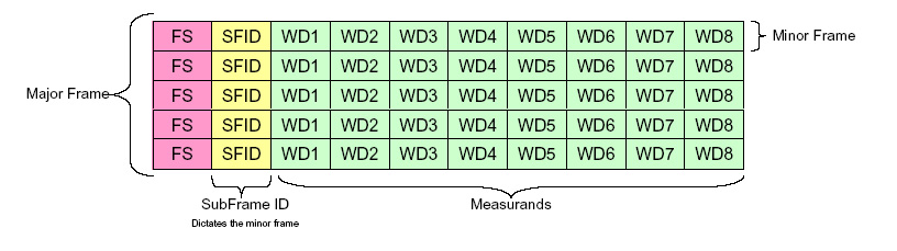
To fully organize the transmission, all the words are put into a frame as seen in figure 3. The figure shows two frame classifications: major and minor. One major frame can be thought of as one complete data package, i.e. a complete set of data from all included sensors. A minor frame, on the other hand, is a set of a certain amount of data—usually it contains some or all data from the different sensors, depending on the commutation which is described below. Each minor frame also includes a word called the frame sync, or frame synchronization. This is a string of data that is always constant, and it is used to identify the start of a new minor frame. Additionally, the minor frame typically includes a frame identification, which for the student rocket is a simple counter increasing by 1 for each minor frame that is transmitted.
Commutation
In the case where a minor frame includes all the data from all the sensors, the major and minor frames are equal. However, it is often the case that some sensors need more or less time to transmit its data than what is reasonable to include in a minor frame. If this is the case, the words containing the data from the given sensors must be commutated. Figure 4 gives the idea of how words can be either sub commutated or super commutated.
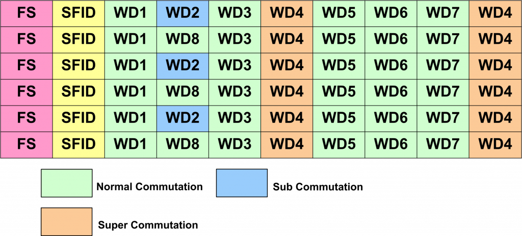
As seen in the figure, word 2 (and technically also word 8) are only transmitted every 2nd minor frame. This is denoted as a 1:2 commutation. Likewise, word 4 is transmitted twice every minor frame, and is therefore commutated 2:1. This technique of commutating words is useful for example if the transmission consists of data from sensors with different sampling rates, where one sensor might not update quickly enough to send new data in each minor frame. It is most common to determine the major frame by the number of minor frames needed to send every word once. This number can be found by the smallest common denominator for the commutations.
<< Previous page – Content – Next page >>
This article is part of a pre-course program used by Andøya Space Education in Fly a Rocket! and similar programs.