The CanSat Kit details and components list
The version 6.2 sensor shield card has been developed at the University of Aalborg by Professor Jens Dalsgaard Nielsen and Simon Jensen and is a slightly revised version of shield version 6.1.

The difference between the two versions 6.1 and 6.2 is that two extra jumpers have been included. With the version 6.2 it is possible to choose between supply voltage of 5V and 3.3V for the GY-component.
The shield has been designed to include:
- Communication radio (APC220) with antenna
- Temperature sensor (NTC 10k)
- Digital 10-DOF sensor GY-91 or GY-80/87/88
- SD storage card (OpenLog)
A parts list is shown in the figure to the right. Click on the figure to get a larger version.
The sensor shield is designed to fit on top of the Arduino Uno R3 Board as shown in the figure below.
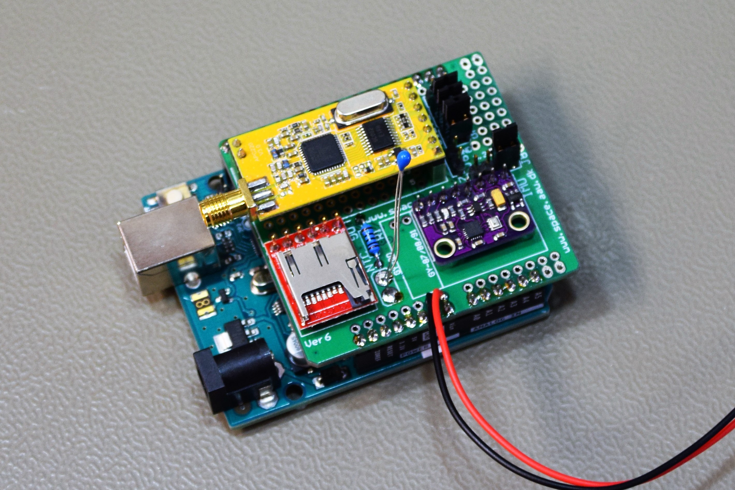
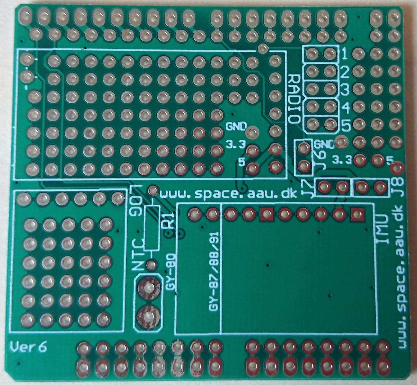
The figure to the right shows the version 6.2 CanSat shield. As seen in the figure, there are 8 places to place jumpers. The purpose of the jumpers is explained in the figure below. Click on the figure to get a larger version.
When J2 and J3 are not connected, you can program the Arduino via the USB cable.
By setting the jumpers at J2 (and J3) you can transmit data through the radio.
When placing jumpers at J4 (and J5) you enable data storage in the MicroSD-card (if a MicroSD card is inserted).
When placing a jumper at J6, the EN pin on the APC220 radio module is connected to the digital port D7 on the Arduino.
A jumper must be placed either at J7 or at J8 or both in order to connect power to the Gy-87/88/91.

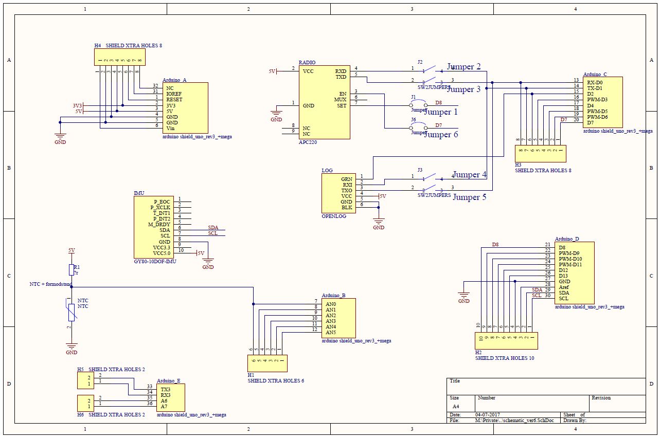
The schematics for versjon 6.1 is shown in the figure below. Click on the figure to get a larger version.