Assembling the Components and Constructing the CanSat-shield v.6.2
This section will show you step by step how to assemble the components for the CanSat shield version 6.2.
Parts list
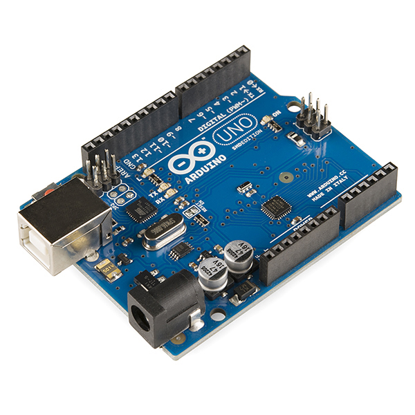
Arduino Uno R3
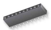
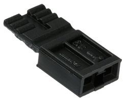
Header socket (Female pin connector) 7-pin and 2-pin
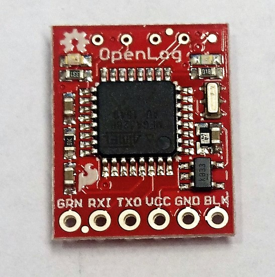
OpenLog Data logger (and an SD-card)
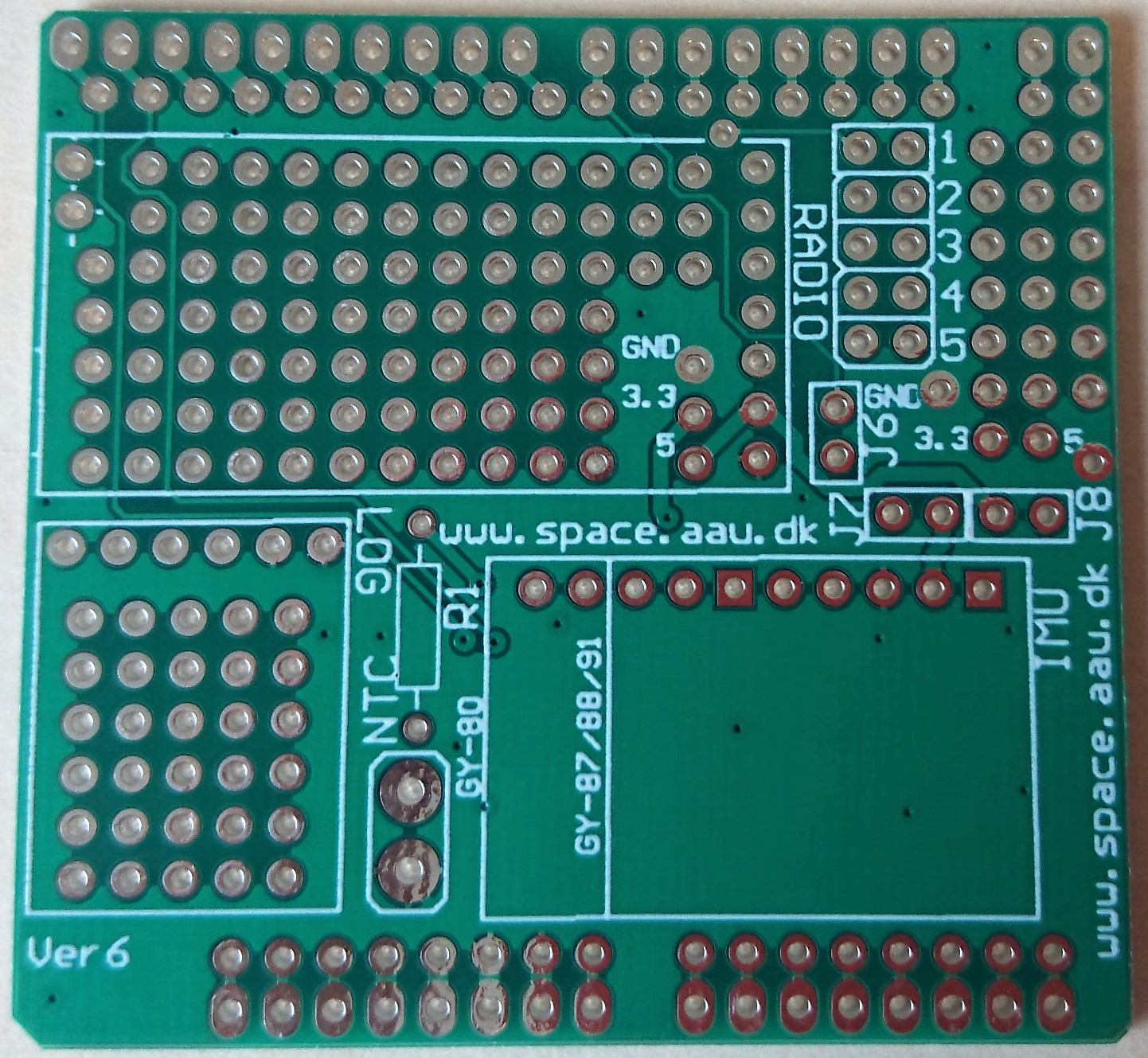
CanSat Shield vs. 6.2 (Circuit board)
Jumpers
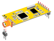
APC220 Radio transmitter/receiver

Temperature sensor NTC (NTCLE100E3103JB0)

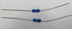
Resistor 1 x 10 kOhm (resistors in the photo is just examples, make sure to choose a resistor with the correct resistance)
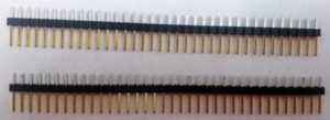
Header (Male pin connector) 2 x 32-pin
GY-91 – 10 DOF multi sensor module with MPU-9255 and BMP280

Assembling guide
1.
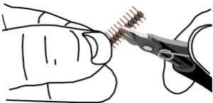
Cut the header in to the following lengths:
– 6 pins (H1)
– 10 pins (H2)
– 8 pins (H3)
– 8 pins (H4)
2.
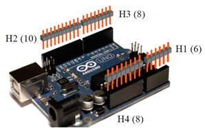
Insert the headers into the Arduino board with the short end up.
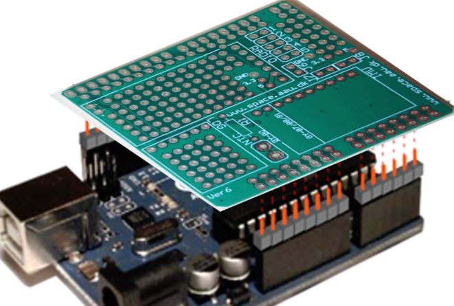
3.
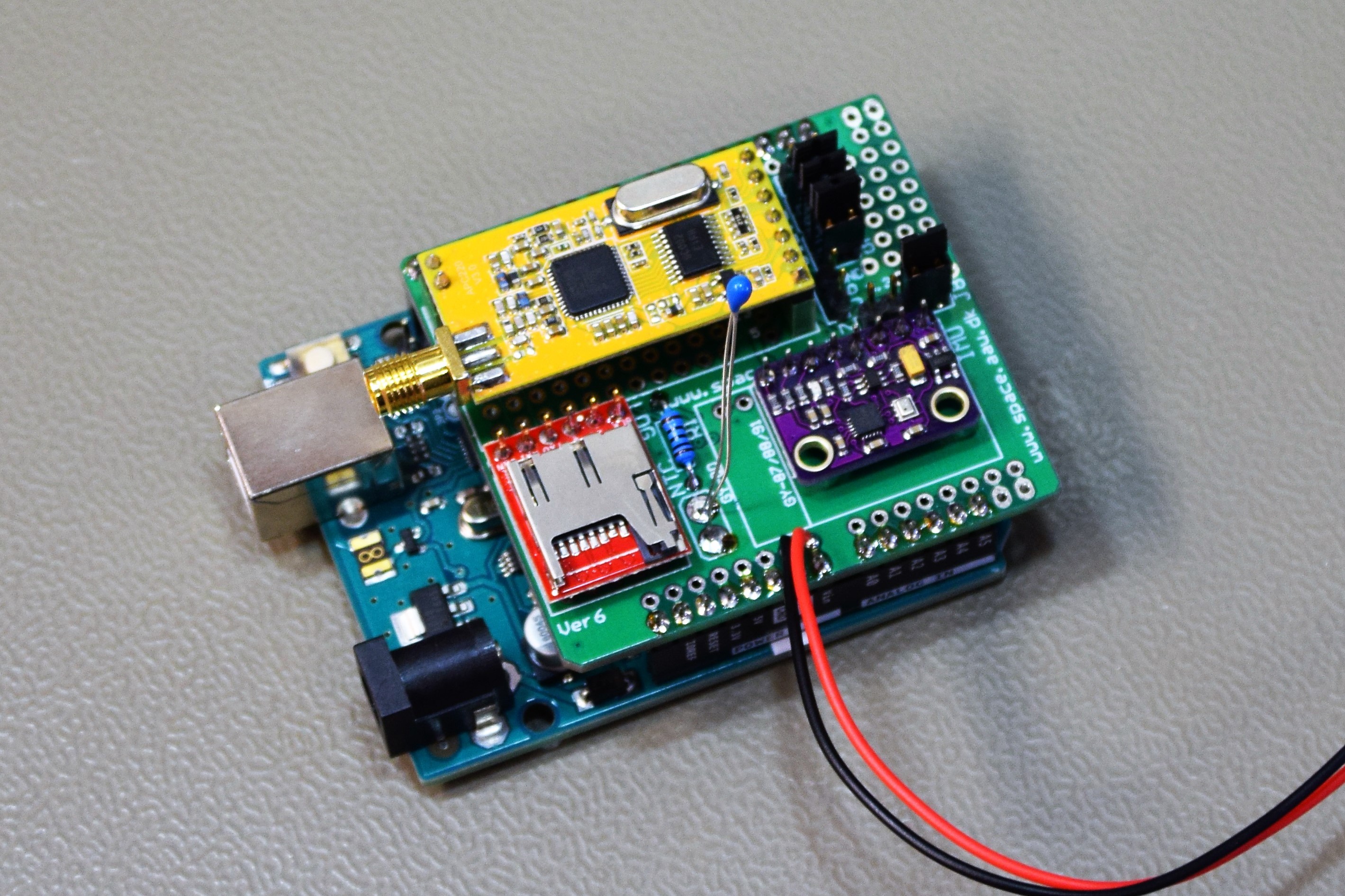
Mount the shield board on top of the Arduino Uno.
Note: The board should fit only one way.
4.
Solder all the pins on the top of the circuit board and then remove it from the Arduino Uno. Make sure not to heat the pins too long while soldering. Too long exposure to heat might damage the Arduino board.
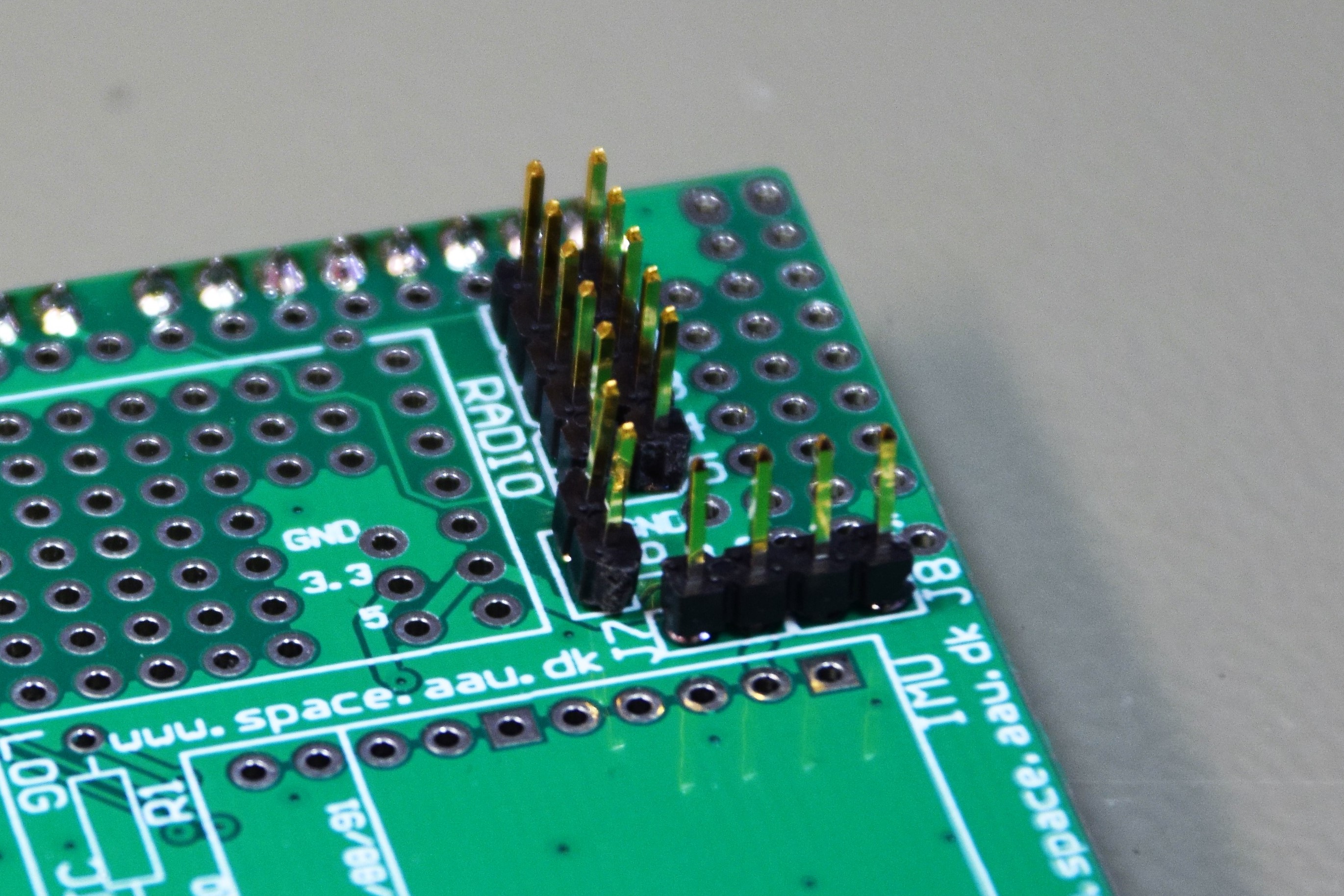
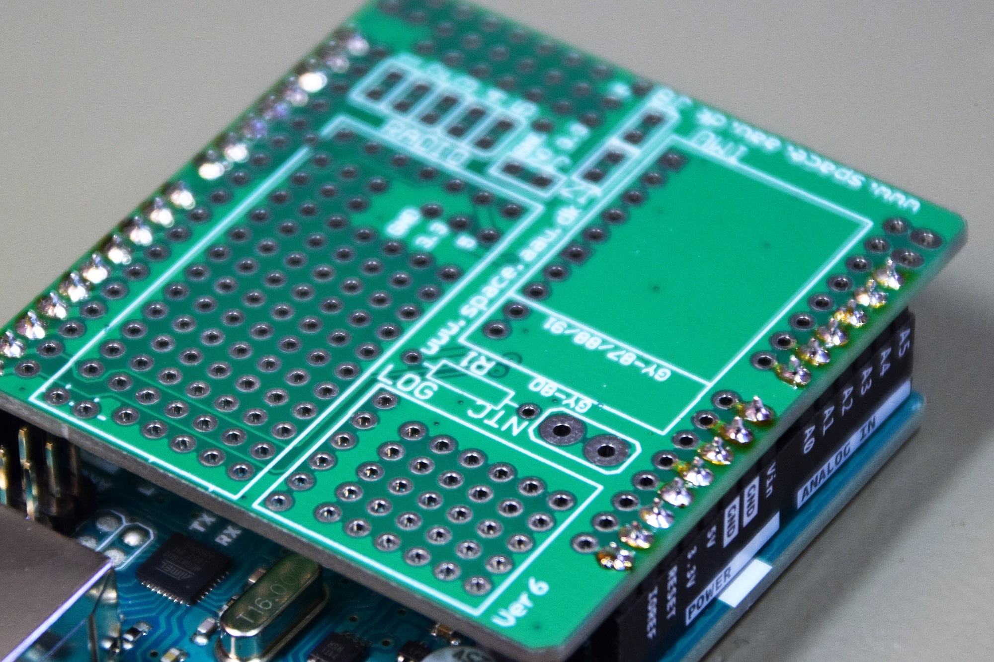
5.
Cut out two lengths of 5-pin header, one length of 4-pin header and one length of 2 pin-header.
Place them on the top of the shield board and solder them on the bottom (soldering side) as shown in the illustration. (Placed at the J1-J5, J7 and J8 position).
To keep the 5-pin headers in place when soldering, it can be useful to put in 2-3 jumpers across the headers.
6.
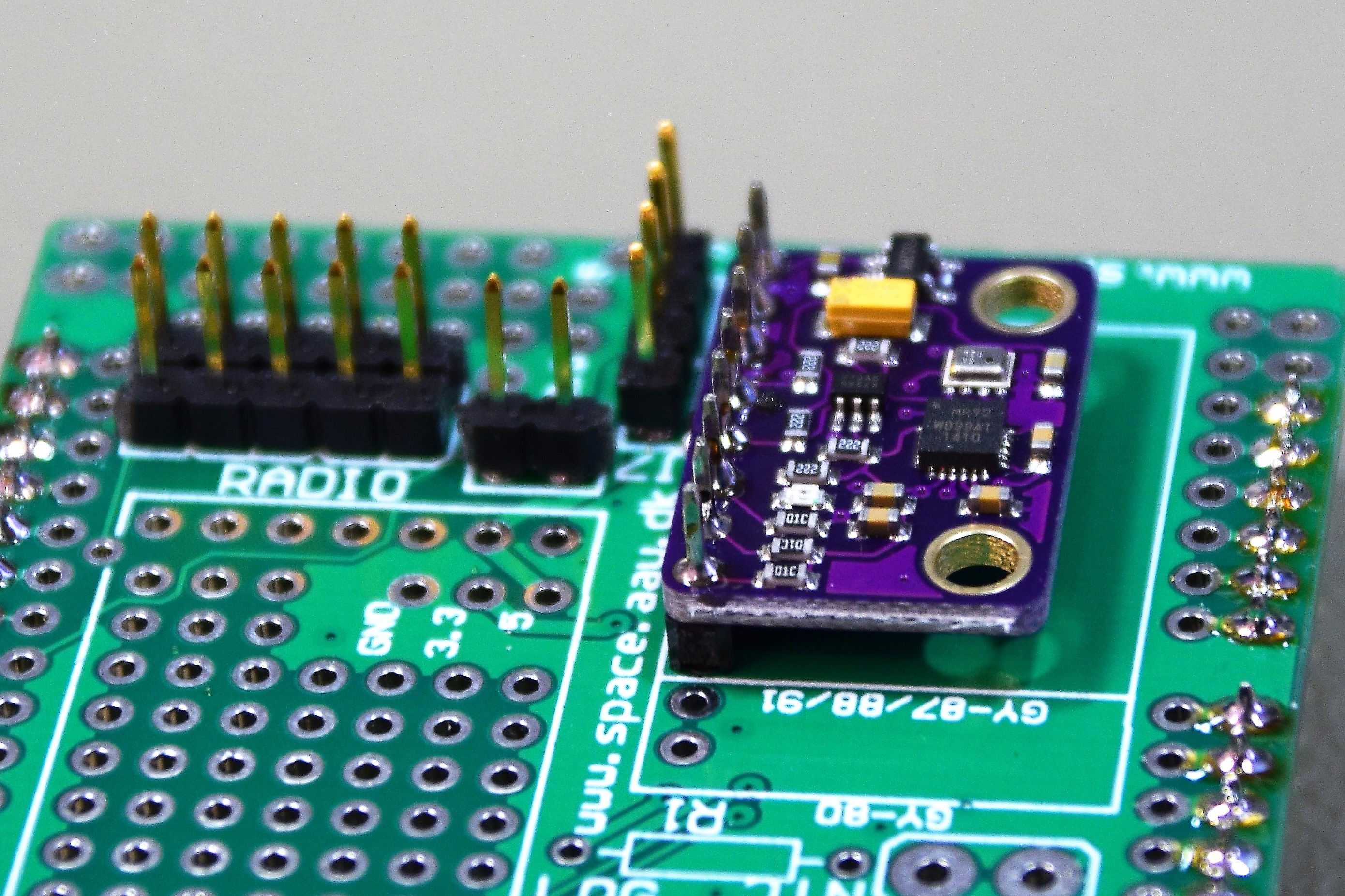
Solder the GY-91 (or Gy-80/87/88) onto the shield board using a 8-pin header (or 10-pin for the GY-80).
Use the short end of the header downwards trough the shield board.
Make sure you place the GY parallel with the shield to get the direction of the sensor x-, y- and z-axis parallel and/or orthogonal to the shield.
7.
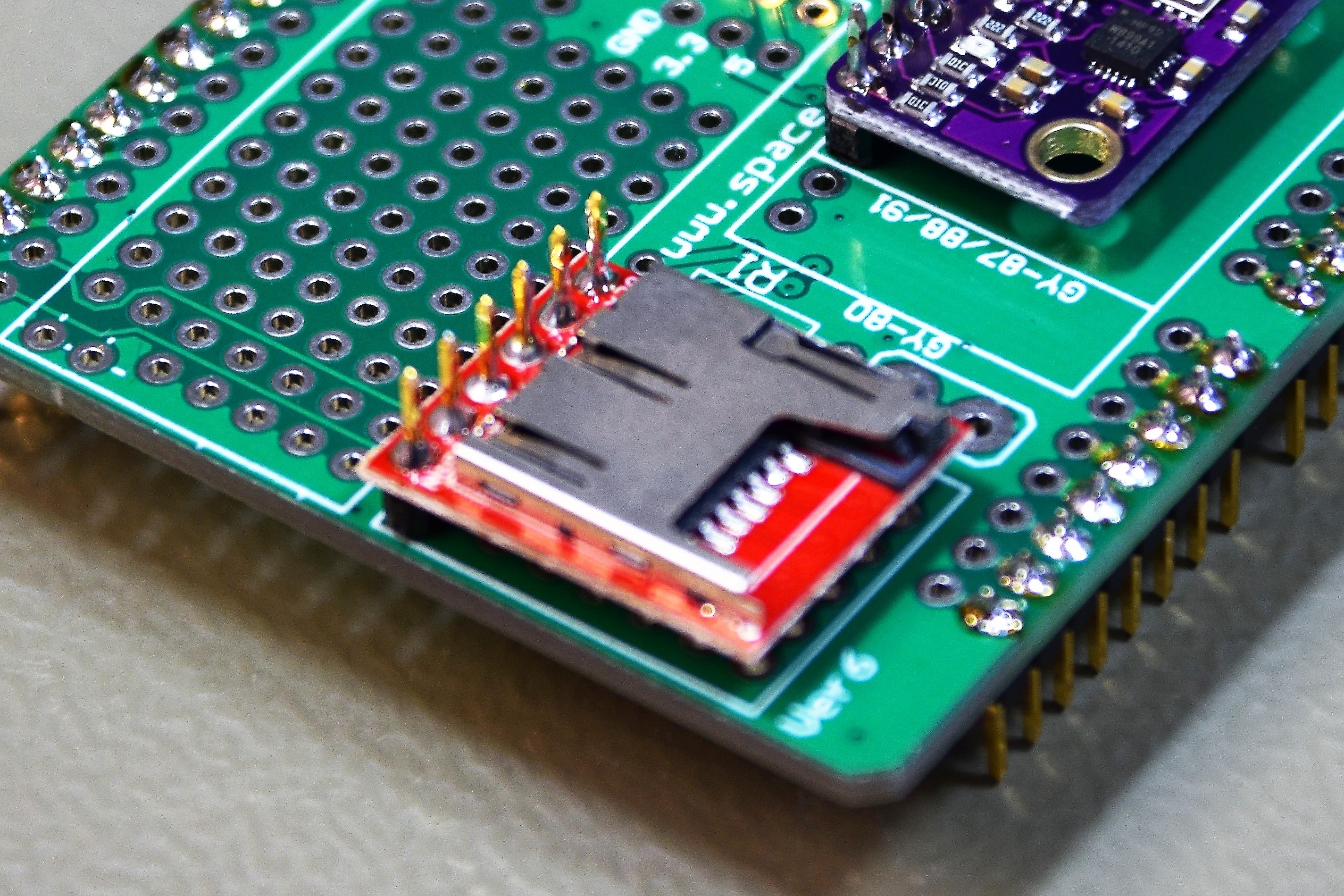
Solder the data logger onto the shield board using a 6-pin header.
Use the short end of the header downwards trough the shield board.
Make sure you place the logger the correct way (See illustration).
It is recommended to use some hot glue in between the board and the logger to support the logger.
If not supported it may easily brake off or damage the soldering Points.
8.
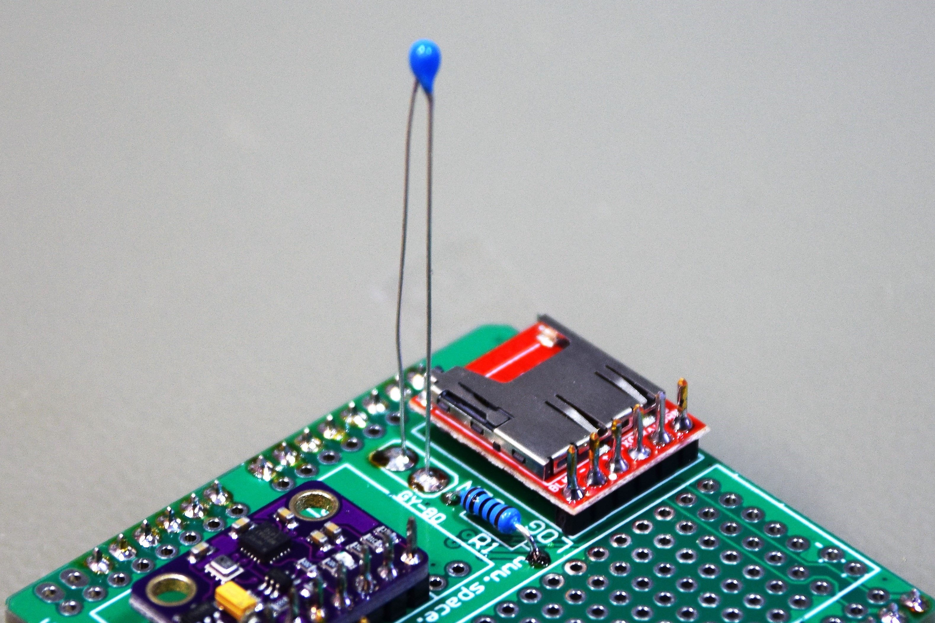
Solder the NTC temperature sensor and the 10k Ohm resistor to the shield board.
9.
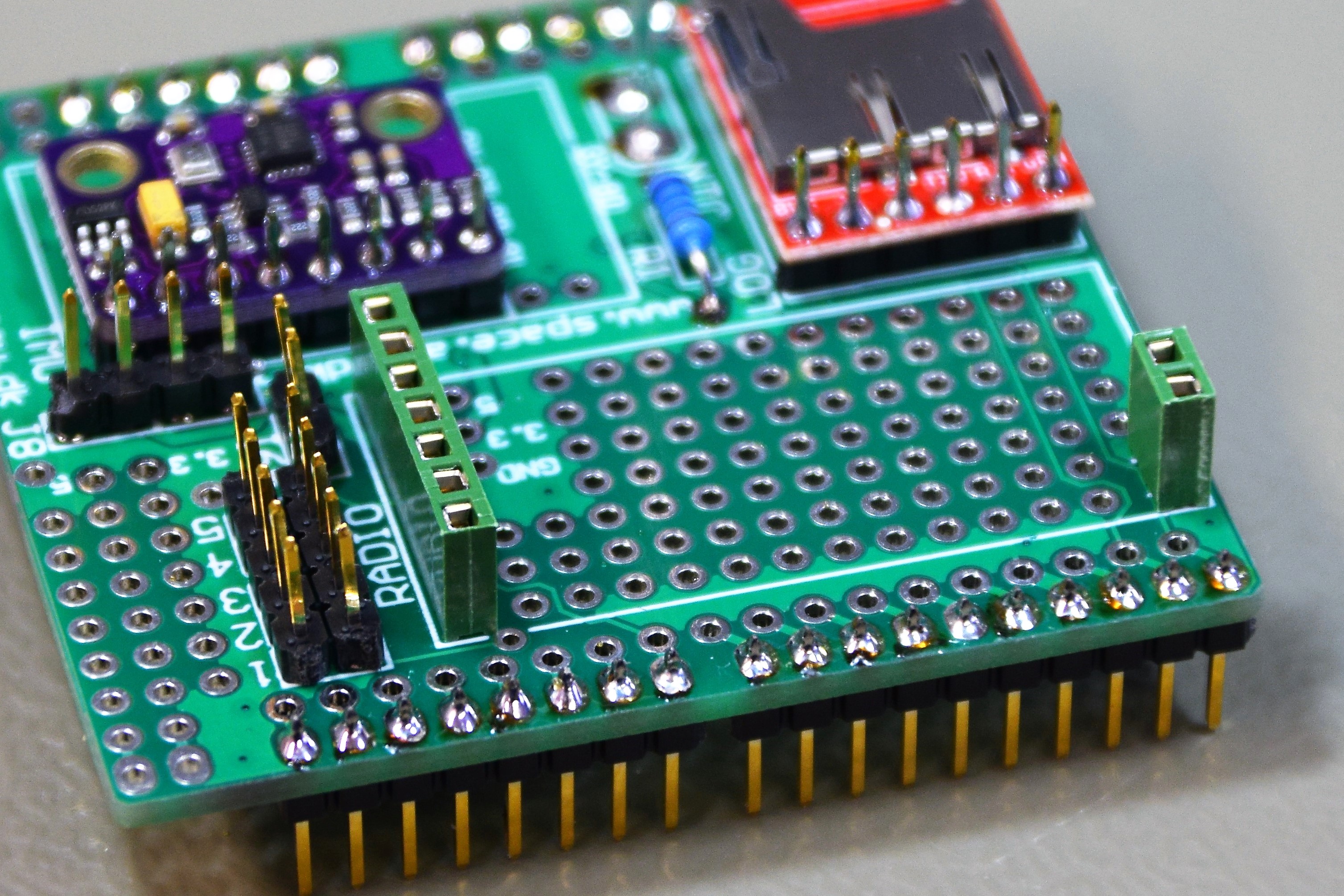
The header sockets allows us to easily connect and disconnect the radio for programming.
Place the two sockets on top of the board and solder them at the soldering side.
If you are unfamiliar with this kit, it is highly recommended to use the header sockets.
This may if necessary be removed to make it more robust.
10.
Solder a 2-pin header to one of the radios.
These pins will only be used as support to reduce the strain on the radio connector.
Mount the radio to the shield board.
11.
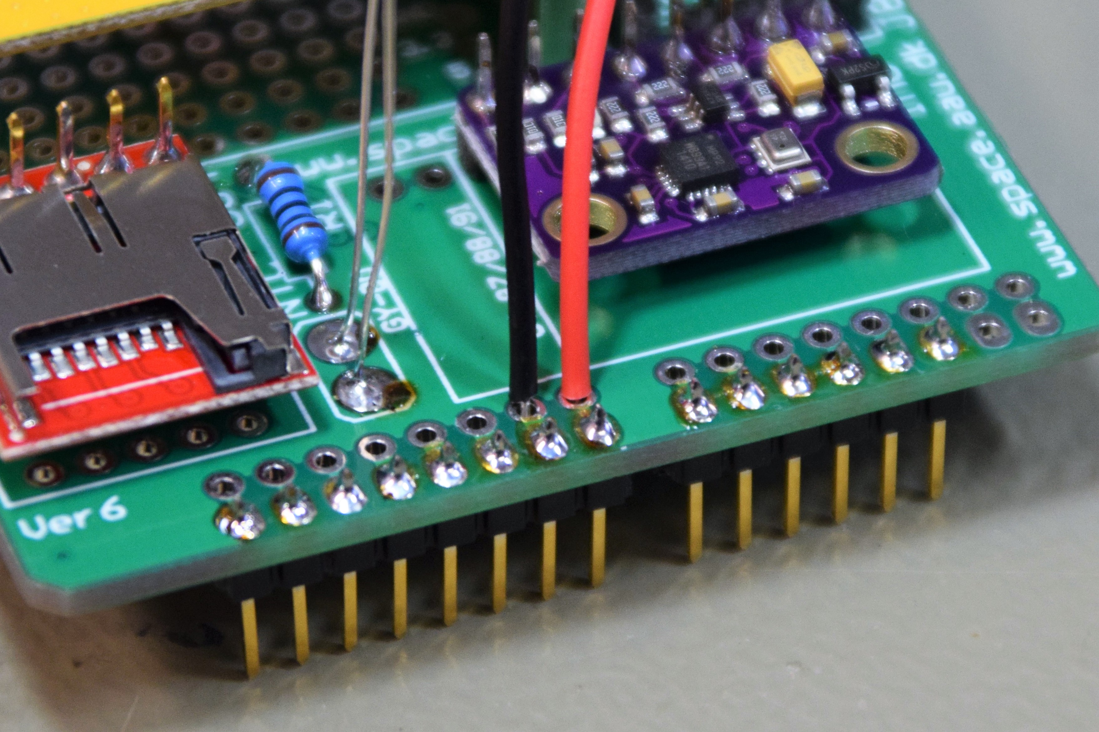
Solder the battery connector to the shield board. Red wire to the Vin port and the black wire to GND port.
The wire connection points will break off easily.
To avoid this you can use hot glue to glue the wires to the board, reducing the strain on the connection point.
The CanSat shield board is now ready to be tested.