About Arduino and inputs/outputs
The kit is based on an Arduino compatible development board called Teensy. This means that, other than the name, the board is to be viewed as an Arduino and programmed as such. The programming language that is used is C, but in a «variant» of it which is often reffered to as it’s own language, Arduino, but is really a set of libraries hidden to the user to make programming of the Arduino boards easier to learn and use. Often programs that are written in Arduino can be used across many boards as they are ment to be as cross-compatible as possible, but some of the features of one boards is not existing on others, so there are exceptions to this. This will be the same for you when using the Teensy.
On the Teensy there is many pins that can be connected to external peripherals and devices. The pins can work in two ways: as inputs and outputs. If the pin is used as an input, the program measures what the voltage level is on the pin and returns that to the user. If the pin is used as an output, the user tells in the program what the voltage level should be on that pin and the microcontroller actually forces that voltage to be that value (either digital or analog, see below).
The Teensy is more powerful than most other Arduino boards, and all pins has more than one function. The pin functions can be divided into two categories: digital and analog. The digital pin functions can measure digital input and also output digital values. Digital values are either high (also often given as a ‘1’) value, in this case 3.3V, or a low value (often called ‘0’) with a voltage level of 0 volts. When it measure/samples a pin, that is measuring what the voltage is on that pin, it measures a high/true/1 if the levels are 3.3V or close to it. If it measures 0 volts or close to it, it registers it as a low/false/0. If the voltage is, for some reason, not close to either 0 or 3.3V however, the output can be either registered as a high or low, dependent of several factors. Computers live in a digital world and the usages of only measuring binary/digital values are huge, and one advantage is that it is extremely fast: the Teensy can output/input a digital values in less than 10 nano seconds!
If you want to measure or output not only digital values, the Teensy has two special internal peripherals called Analog to Digital converter (ADC) and a Digital to Analog Converter (DAC). Since all microcontrollers (which is essentially a simplified miniature computer) can only handle digital values the ADC and DAC works as an interface to an analog world: the ADC on the Teensy measures up to 4096 (12 bit) different linearly spaces analog values between 0 and 3.3 V. The DAC works in the completely opposite way: it takes a 12-bit value from the program and forces the pin to be on that value until it is changed by the user to another value. The Teensy has one ADC (technically three ADCs, but dont worry about that as they look like one for you as a user) and one DAC. However, that ADC and DAC has many channels, so even though it can only read input/output one at a time, it can work on many different pins. The DAC has only two pins (called DAC0 and DAC1) but the ADC has 26 channels/analog input pins, where 19 of them are available to you as a user (some is used for functions on the NAROM 2018 kit already and some are on pins that are not easily accessable).
We have discussed digital input/output pins already, but it is a sub-category of digital pins we have not yet talked about. There are only two voltage levels on digital pins, but the voltage levels can vary in time in many (infinite) different ways. The most popular way to communicate with the outside world is through serial communication: this is where one or a few pins vary dependently on each other in a very specific way based on some standard. You are guaranteed to have heard of USB communication: this is a serial protocol with two wires working together as one output in a special way (if we dont consider the new variants) to communicate in a extremely fast, standardized fasion between devices. In the embedded world of microcontrollers there are numerous other serial communication standards, with UART, SPI and I2C as one of the more famous/widespread, but all of these work with the same basic idea: alternating one/few pins in a specific way in time makes communication fast, cheap and simple. There are reasons not to use parallel communication which was very popular in the 80s and 90s which we will not come into here.
Installing software
Firstly, you need to download the Arduino IDE. An Integrated development environment (IDE) is a type of software running on a computer that is made to simplify programming of devices. The Arduino IDE is both used to write the code to be uploaded to the Arduino/Teensy boards and uploading the code itself to the bord. The IDE has built-in compilers and everything else needed to upload the code and will do that in the background when you tell it to do so. Download the latest Arduino IDE here. There are two downloads for Windows: the Windows installer which installes the IDE on the computer and administration rights is needed and a ZIP file in those cases that you dont have administration rights and need to quickly need to get started. The installer is preferred, but the zipped works fine but is a bit more hassle to use. Avoid using the Arduino Web Editor.
You will also need the Teensyduino, which is a small add-on to the Arduino IDE to simplify programming your Cansat. It can be downloaded here. There are options for Linux and Mac for both Arduino IDE and Teensyduino, but we will not discuss that here.
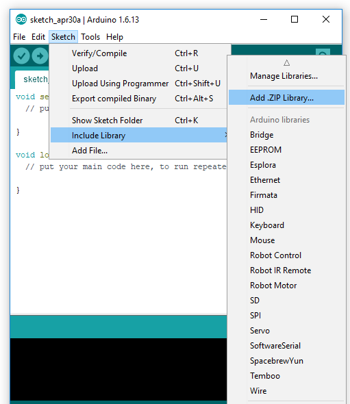
After installing the Arduino IDE and Teensyduino, run the IDE. NAROM has written two libraries to simplify working with the Cansat kit. Download the libraries for the transceiver here and the GY-91 sensor here and save them to the hard drive. In the Arduino IDE, klick the «Sketch» menu, further into «Include library» and press «Add .ZIP Library…». The menu will then prompt you for the location of the zip files, but choose only one of them and press OK, and the Arduino IDE will import the library. Do this for both libraries, and you should be good to go.
Connecting the Cansat board and upload the first program
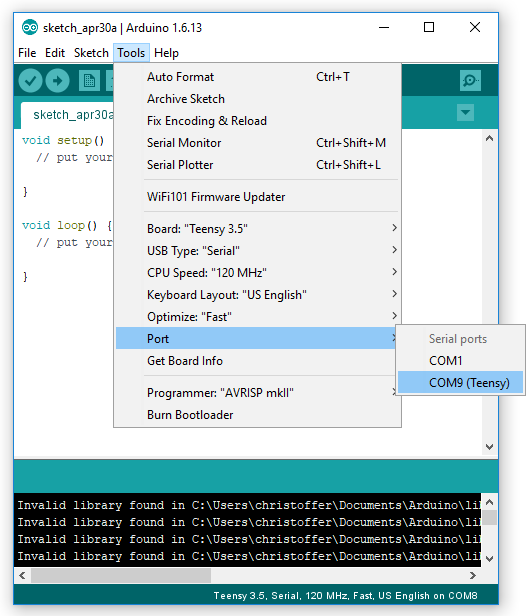
Connect the Cansat board (or only the Teensy if you have not yet soldered it to the Cansat PCB) using a Micro-USB to USB cable to your computer. This should automatically download the proper driver to your computer and install it. When a new Teensy is connected to power it runs a standard program (called sketch in Arduino) which blinks an orange LED light on the board every second. If this does not happen and the Teensy is brand new (no new program has been uploaded), check the connections and that the Teensy has power and is not short circuited. When Windows have said that the device has been properly installed and configured, go to the Tools menu and Boards, select «Teensy 3.5» (many, many boards can be listed here if you have added them before, but the Teensy boards should also be on the list). After choosing the board, the Tools menu should be changed a bit and look something like in the figure below (dependent of version number). Go then to the Ports sub-menu as in the figure and select the active Teensy. Many different COM ports might be listed here, but the Arduino IDE will automatically detect all Teensy (and other Arduino boards) and list the type of board in parenthesis as seen in the figure. If you have other Arduinos connected, please detach them from the computer first.
After you have properly configured the Teensy board in the Arduino IDE, we can upload our first sketch. Start with a fresh, new program (File -> New…) and press the Upload button (which will store the program, compile it and then upload) as seen in the figure below. If your Teensy was blinking, the blinking should stop after uploading this sketch. An upload progress var can also be seen in the tiny Teensyduino add-on window that should have appered (note that it might be hidden behind other windows you have on your screen). If the upload was not a success, a error should appear in the bottom of the Arduino IDE in orange text stating:
«Teensy did not respond to a USB-based request to automatically reboot.
Please press the PROGRAM MODE BUTTON on your Teensy to upload your sketch.»
If you have checked that the Teensy is properly connected and configured in Windows, try uploading the sketch again and press the button on the Teensy board (the physical board) at the same time (a single tap is enough). It is very rare that this is needed, so if you got an error message, it is more likely that there is something wrong on your end (either bad connections, wrong configuring or power issues).