Assembling the Components and Constructing the v2018 CanSat-shield
This section will show you step by step how to assemble the components for the v2018 CanSat shield.
A list of components and link suggestions for ordering the components can be found here.
Parts list
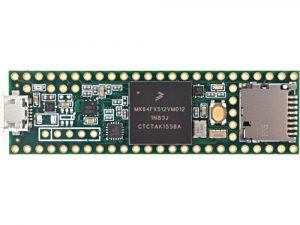
- Teensy 3.5
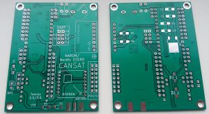
- CanSat Shield v2018 (Circuit board)
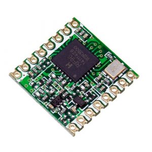
- RFM96 Radio Module
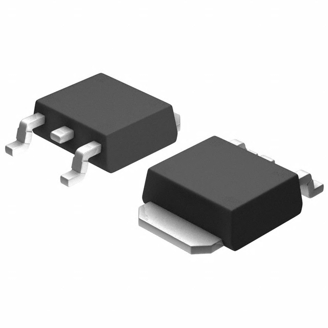
- Voltage Regulator TO252-3. This voltage regulator can be used with batteries voltages up to 5.5V . If you choose to use for example a 9V battery in stead of the 3.7V Lipo battery suggested below, you need to use another voltage regulator. A link can be found in the components list above.
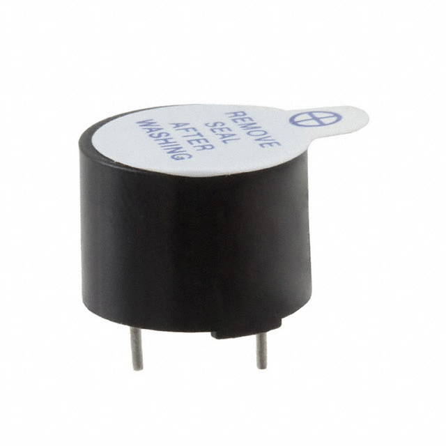
- Buzzer
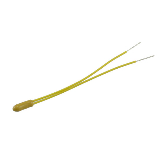
- Temperature sensor NTC (NTCLE300E3103SB)
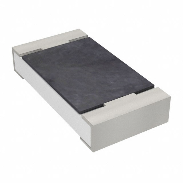
- Surface mounted 1206 resistors (5 · 4,7 kΩ and 1 · 470 Ω)
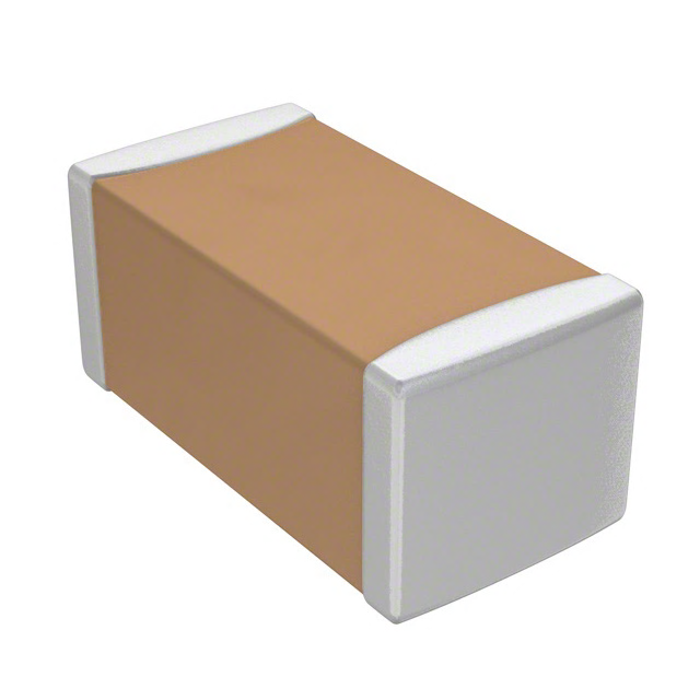
- Surface mounted 1206 capacitors (2 · 10 μF and 2 · 1 μF)
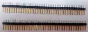
- Header (Male pin connector) 3 x 32-pin
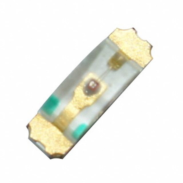
- Light diode
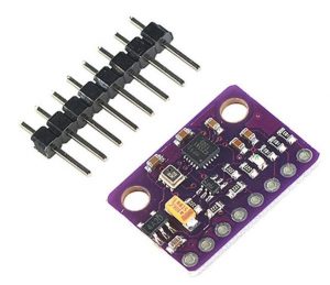
- GY-91 – 10 DOF multi sensor module with MPU-9255 and BMP280
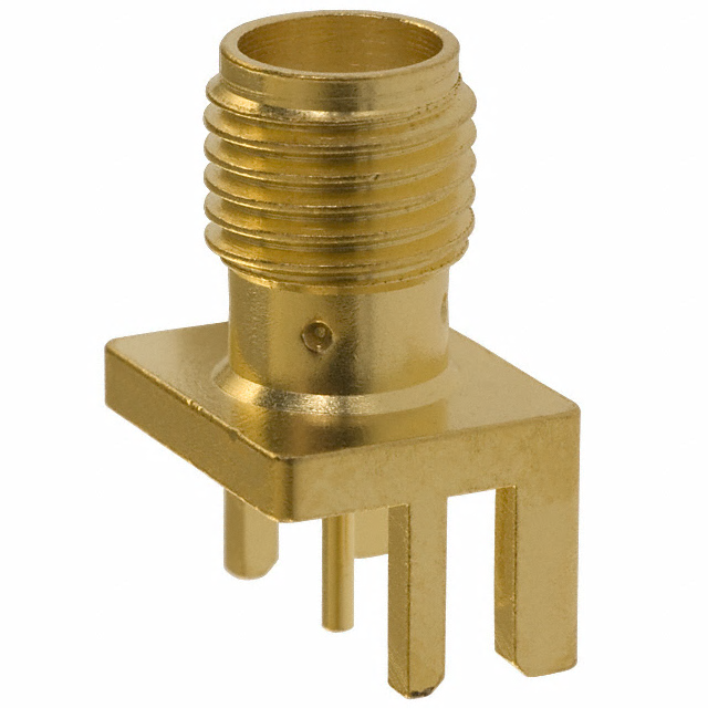
- Sma connector
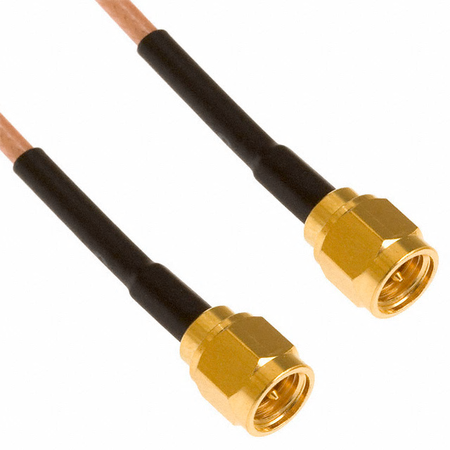
- Sma cable for antenna
Power Supply (Battery)
(This type and size of battery is optional, but will for convenience be included in the v2018 CanSat kit on courses/workshops by Andøya Space Education):
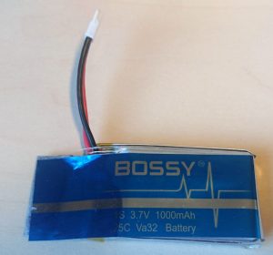

- Li battery 3.7V 1000 mAh
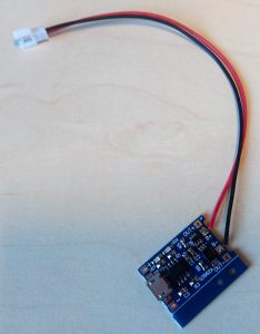
- Battery charger for micro USB cable and and a DIY JST DS LOSI 2-pin connector plug with wire
- Battery connection wire
Assembling guide
Note that the pictures shown in this section was taken of a previous version of the v2018 kit. You will find a few discrepancies from your version, but will be able to assemble the board anyway. The resistors in the pictures may not have the same value or number as stated in the text, so in case of descrepancies follow the instructions in the text.
1 
2 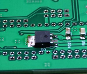
3a 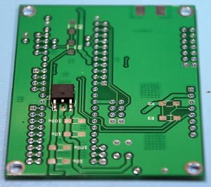
3b 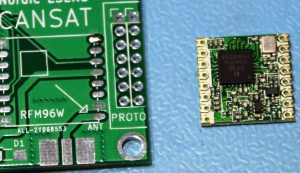
4a 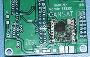
4b 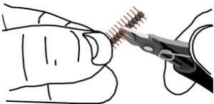
5 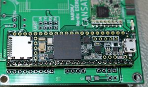
6a 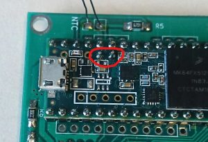
6b 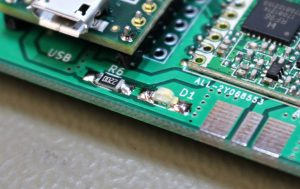
7a 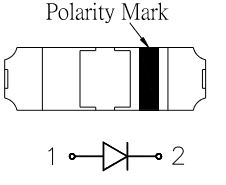
7b: Light diode polarity. 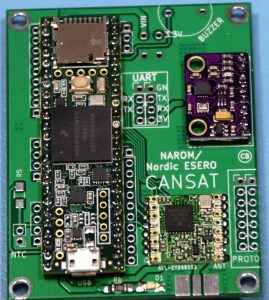
8 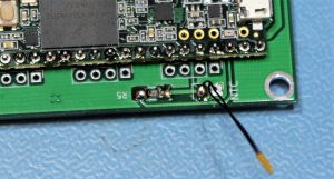
9 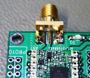
10a 
10b 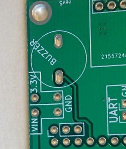
11a 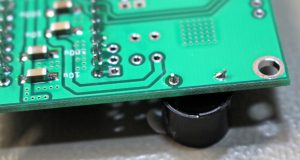
11b 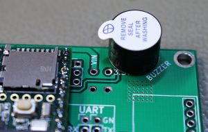
11c
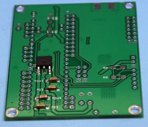
1. Solder the 4 capacitors onto the backside of the board:
C1 and C3: 10 μF
C2 and C4: 1 μF
2. Solder the four 4,7 kΩ resistors onto the backside of the board on the places named R1, R2, R5 and R6.
R1, R2, R5, R6: 4,7 kΩ
3. Solder the voltage regulator to the backside of the board. Position: U1
Both the two pins on one side of the regulator and the larger ground plane on the other side of the voltage regulator has to be soldered to the board as shown in the figure to the right.
4. Solder the radio module onto the board (on the upside of the board). Be sure to place the radio module in the right orientation.
A square shows where the black chip on the radio should be situated.
5. Cut headers to the following lengths:
– 24 pins
– 24 pins
– 8 pins
– 2 pins
6. Solder the Teensy 3.5 onto the board using two 24-pin headers and one 2-pin header.
Put the headers and the Teensy in place on the board:
The end of the Teensy holding the USB-connector should be placed as indicated on the board.
The 2-pin header is used for connection to the NTC. See the red drawing in the picture to the right.
Solder then first the Teensy to the 2-pin and 24-pin headers
and afterwards the pin headers to the board at the back side of the board.
7. Solder the light diode (D1) and the R4 resistor onto the board. (R6 in the photo is wrong and should be R4)
Light diode polarity: The (green) marked end of the diode must point towards the D1 pad on the pcb.
R4: 470 Ω
8. Solder the GY-91 onto the board using a 8-pin header.
Use the short end of the header downwards trough the board.
Make sure you place the GY-91 parallel to the shield to get the direction of the sensor x-, y- and z-axis parallel and/or orthogonal to the board.
9. Solder the NTC temperature sensor and a 4.7 kΩ resistor onto the board.
R3: 4.7 kΩ
10. Solder the sma connetor onto the board.
Remember to solder on both sides of the board.
11. Solder the buzzer onto the board:
Put the buzzer legs through the holes in the board and solder on the back side
12. Solder the battery connection wire to the board.
Solder the red wire of the «battery connection wire» to the board at VIN and solder the black wire to the corresponding position marked GND. Only use batteries with voltages up to 5.5V, or change the default regulator to another that can handle voltages higher that 5.5V.
Attach a small amount of hot glue to the board where you soldered the wires. This will prevent the battery wires to break too easily.
If you have chosen to use an external voltage regulator, you can use the position marked «3.3V» in stead of the VIN position.
Ground Station:
For the ground Station, you will need another empty CanSat board and only equip it with:
- RFM96 radio module
- Teensy 3.5
- sma connector
- An antenna (for example an 1/4 λ-wire antenna or a YAGI antenna)
When working as a ground station, the Teensy 3.5 will be connected and powered via an USB cable to your pc, and needs no voltage regulator or other components on the board, except the radio and sma connector.
The CanSat shield board is now ready to be tested.
