The Andøya Space Education v2018 kit was made to deal with some of the more negative sides of using an Arduino based kit. The benefits of using an Arduino Uno and a shield on top of it, is that it is familiar to many that have some experience with Arduino, since the Uno is what most people start of with when playing with Arduinos. Also, it has a physical size/pinout that many shields are using.
The drawbacks, however, is many. It is a 5 volt based system, which in some cases when using older sensors is a benefit, but most sensors, especially digital ones, are 3.3v based and hence you do need an interface/buffer between a 3.3v based sensor and the Arduino to use it. All Arduinos except the large Zero (48 MHz) and Due (84 MHz) are relatively slow, running on a 8/16 MHz CPU and relatively expensive compared to what you get. Some Arduinos do not have built-in USB interface, so it uses a USB chip (most often a secondary MCU) which is slow.
The Teensy 3.5 based v2018 kit tries to solve these issues. It is a based on a 3.3V system running on a Cortex M4F core with 120 MHz nominal CPU speed (which is overclockable, but this is normally not needed working with Cansat). It has 23 analog input channels (where 19 of these are available to the user on the Cansat kit) and 2 analog outputs (DAC0 and DAC1, which share pins with A21 and A22 channels). True analog outputs are not available on any of the Arduino boards except the Arduino Zero and Due. All GPIO pins are 5V tolerant (which is not true on the pin compatible Teensy 3.6 board). And it has a built in micro-SD card SDIO interface that runs up to 20 MB/s! Also, it is a true 12 Mbps USB device.
You can find the schematics (pin-out diagram) for the Andøya Space Education v2018 CanSat here.
As already stated, the Teensy 3.5 is 5V tolerant device on all general purpose input/output pins (GPIO), meaning that you can put 5V on the inputs. It can only output 3.3V, of course, but it can handle inputs up to 5V. However, note that the ADC is not 5V tolerant, so never put anything over 3.3V input on the ADC pins!
Teensy 3.5 pinout
The Teensy 3.5 has many advanced functions that we will not state here. If you would like to read more about them, please see the pinout page, the Sparkfun product page and the PJRC (which manufactures the Teensy boards) forum which is excellent.
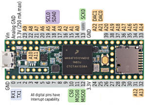
In Figure 2 you can see the name and place of the Teensy 3.5 board pins that are the most relevant for the Cansat kit.
Purple pins are I2C, green is SPI, blue (RX1 and TX1) is UART, orange is analog (marked A0 to A22) and digital (marked DAC0 and DAC1) and the grey is GPIO. As you can see, some pins are multipurpose. Almost every pin can be used as GPIO, but only a few pins can be used as I2C, SPI and UART, and almost half of the GPIO pins can also be used as analog pinouts.
Please note that the Cansat kit has some specific uses of some of the pins, especially the SPI pins which are used by the radio. If you need SPI, you could in principle use the SPI0 bus, but life is going to be simpler for you if you use the SPI1 bus available on pin 0 (MOSI1) , 1 (MISO) and 32 (SCK), which can be seen on the general pinout page).
Version 2018 kit components and pins
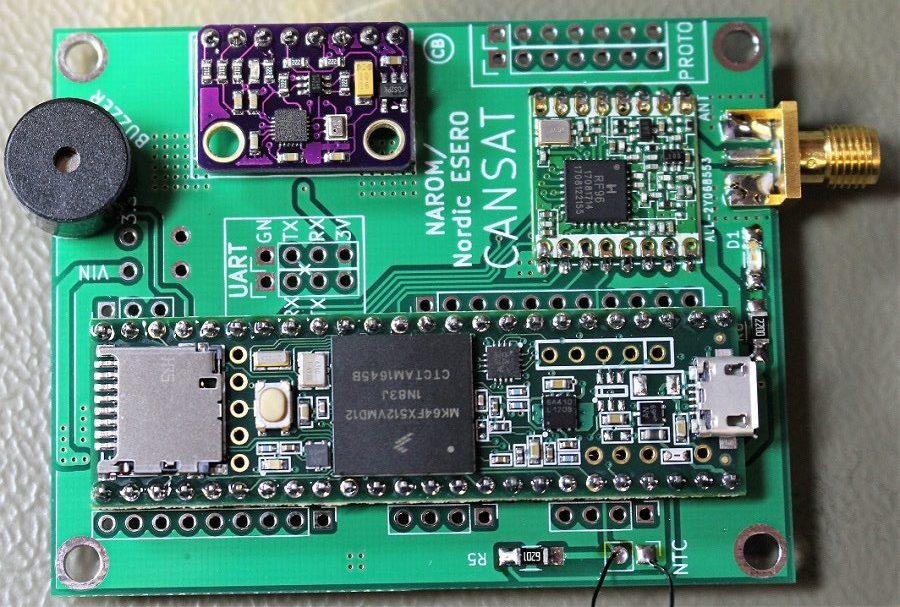
The completed kit seen in Figure 1, you can see the Teensy 3.5 on the bottom side of the PCB. On the Teensy you can see the USB port on the right side of the figure, the microcontroller in the middle (the black square with text on it) and the micro-SD card mount on the left side. The buzzer, marked with text, is on the top left on the Cansat PCB and is free to be controlled by the user by GPIO. Here you can find the components list for this Andøya Space Education v2018 Cansat kit.
On the top right side the radio can be seen, and on the far right side the antenna SMA connector can be seen. The radio has a dedicated article (here) in the CanSat book documentation and will not be described further here. On the top middle, the GY-91 (IMU+pressure) board can be seen in a purple PCB color. This has a BMP280 pressure sensors and a 9 DOF MPU9255 IMU which has 3-axis accelerometer, 3-axis gyro and 3-axis magnetometer.
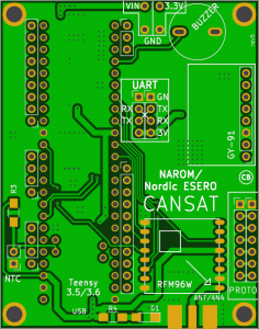
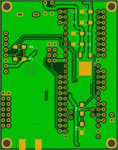
Graphics of the clear PCBs can be seen in Figure 3 (top) and Figure 4 (bottom). As can be seen in Figure 1 and 3, many of the Teensy pins have an adjacent pin that you as a user of the Cansat kit can control as much as you would like. There are pins that are not broken out with an adjacent pin, however, and these are either for power (5V when connected to USB, Vin, 3.3V or Gnd) or for functions already in use by components on the Cansat kit. These functions are SPI0 for the radio, I2C0 for the IMU/pressure board and GPIO pin 29 for the buzzer. Analog channel A10 and A11 is used for the NTC sensor and for measuring the battery voltage (through a voltage divider).
Alternative pins/busses
Although the Cansat kit uses SPI0 and I2C0 already, you can in principle use this for other uses aswell. However, it is much easier for you to use a dedicate bus (a completely different component on the microcontroller that is independent on SPI0 and I2C0). Both SPI1 (pin 0, 1 and 32) and I2C1 (37 and 38)/ I2C2 (pin 2 and 3) can be used by you. This is also true for the UART which has Serial1 connected to pin 26 and 27 in addition to pin 0 and 1, Serial2 to pin 9 and 10, Serial3 to pin 7 and 8 and Serial4 is connected to pin 31 and 32.