Intro
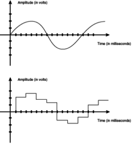
The version 3 CanSat kit used in this manual comes with a sensor board. Connected to this board are four sensors; a pressure sensor, two temperature sensors and a three axis accelerometer. These sensors produce a voltage depending on the value of the parameter the sensor measures. It can take on any value in a certain range; such a signal is called an analogue signal, viewed at the top in the figure to the right. From the measured voltages, we can calculate the corresponding value, for instance converting voltage to temperature.
This section will show you how to convert the analogue voltage measured at the sensor, to the physical quantity with the correct unit.
Analogue to Digital
All digital components operate with discrete signals. Unlike the analogue signal, a signal that can only take on some discrete values is called a digital signal. In the figure to the right these two different signals are illustrated. The top graph shows an analogue (continuous) signal, and the bottom graph shows a digital (discrete) signal.
Desktop or laptop computers, as well as the small computer in the CanSat (called a microcontroller), can only process digital signals. To convert the analogue signal from the sensor into a digital one we use an Analogue to Digital Converter (ADC), which as the name implies, converts an analogue signal into a digital signal.
The ADC converter is incorporated in the microcontroller and has 8 input channels. It is a 10 bit ADC; it will convert an analogue signal into a digital signal with a 10 bit binary number. One Bit represents one binary digit and can have a value of 0 or 1, which also can be represented by High or Low voltage, as well as On or Off. In programming 0 and 1 is also often represented by True (1) or False (0).
Each digit in the binary number can have 2 values, 0 or 1. A 10 bit binary number can have 210 = 1024 different values, and can represent an integer ranging from 0 to 1023. The microcontroller can understand digital numbers and use it for computations, which can be programmed into the processor by writing a program code. An example of such a code is the TestShield-code which was used in the previous part of this manual.
Each sensor in the CanSat is sampled by the ADC, which turns each analogue value into a 10 bit number. 0 volts is converted into the binary number 0000000000 = 0 and 5 volts into the binary number 1111111111 = 210 + 29 + 28 + 27 + 26 + 25 + 24 + 23 + 22 + 21 + 1 = 1023.
By representing the 5 volt input by 1024 levels (including 0) we have a resolution of 5V/1023 = 4,89mV. This shows us that with a 10 bit ADC, the smallest voltage change we can measure is 4,89 mV. This is important to notice when we start working with the sensitivity of the sensors.
The sequence of events using an analogue (temperature-)sensor is thus as follows:
- The temperature sensor converts the measured temperature into a voltage. This is an analogue signal.
- The analogue signal (voltage) from the sensor is connected to one of the analogue ports on the Arduino Board.
- The ADC converts the analogue signal into a digital signal, which the processor can handle.
- Inside the microcontroller the signal is stored as a 10 bit binary number, which can be used for computations or can be transmitted via the Arduino TX port and a radio or USB cable to an external receiver.

