
A transceiver is a device comprising both a transmitter and a receiver which are combined and share common circuitry or a single housing. When no circuitry is common between transmit and receive functions, the device is a transmitter-receiver.
In the Arduino CanSat kit we are using APC220 which is a transceiver, with a highly versatile low power radio solution that is easy to setup and integrate into any project requiring a wireless RF link.
It is perfect for robotic application which gives you wireless control.
You can connect one of these modules with your microcontroller through TTL interface. And connect your PC with another APC220 module through a TTL/USB converter.
Setting up transceiver hardware
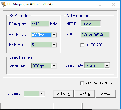
There are two ways of configuring the transceivers. They can be programed directly from the Arduino board, or you can program them by using the RF-Magic software. The start up screen for the RF-Magic program is shown in the figure to the left.
RF-Magic has a lot of bugs, and some computers will have problems getting the program to run properly.
We recommend using the Arduino to program the radio settings as described below.
Installing drivers
The transceiver at the ground station will be connected to the computer trough a USB-TTL converter. This module needs a driver to work properly.
The latest VCP (Virtual Com Port) drivers for the USB-TTL module can be downloaded from Silabs.com (CP210x USB to UART Bridge VCP Drivers).
Follow the link and download the file according to your platform.
When downloaded, unzip the file and run “CP210xVCPInstaller_x64”.
It’s recommended to first install the USB-TTL converter drivers and then plug in the USB converter with the inserted APC module. When the module is inserted, Windows will recognize it and configure the necessary drivers. If Windows does not recognize the device or reports that the device is not functioning properly; remove it from the USB port and reinsert it.
Programming the transceivers with Arduino
Connect the Arduino board to the computer and upload (and unzip) the program “apc220cfg.ino” which can be found here.
Make sure you upload the program before you try to connect the transceiver to the Arduino board. Disconnect the USB cable (and battery) from the Arduino board and connect the transceiver to the Arduino as shown in the figure to the right.
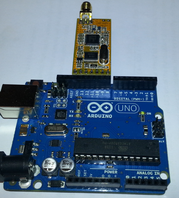
The transceiver will be connected to the pins labelled GND, 8,9,10,11,12 and 13 on the Arduino Board.
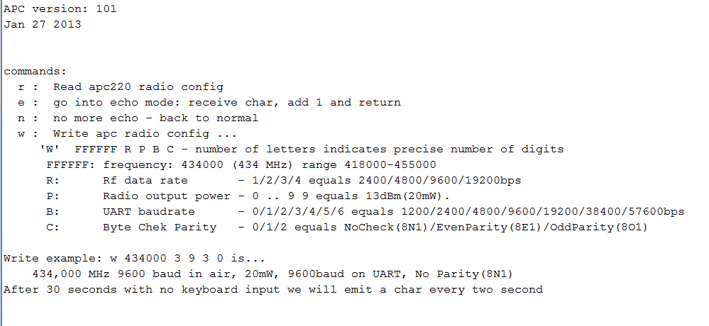
Reconnect the Arduino board trough the USB cable and open the Serial Monitor. In the command line at the top, type in ‘m’ and hit enter. This will bring up the menu shown in figure to the left. Click on the figure to get a larger version.
If you type ‘r’ and hit enter, the program will return the current configuration for the transceiver.
To reconfigure the radio, type ‘w’ and the 5 parameters needed, with space between each parameter.
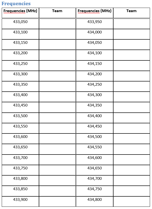
For your CanSat you have been given a pre-set frequency. If not, a list of frequencies are listed here in the figure to the left. Click on the figure to get a larger version. The bitrate should be set to 9600 bps.
Note that you have to configure both transceivers with the same settings to be able to use them together.