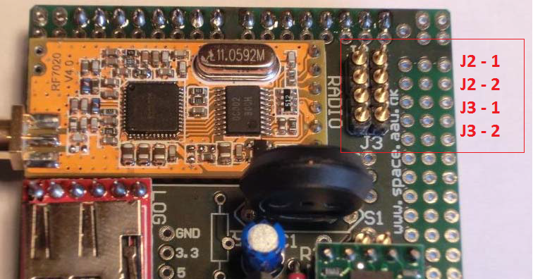
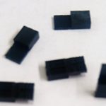
When you are finished programming the v3 CanSat kit you should test that the radio link is working properly. Place jumpers on J2, connect the receiver to the PC via the USB to UART Bridge (USB-converter) and open the Arduino software.
Change the COM-port from Arduino Uno R3 (COMxx) to Silicon Labs CP210x USB to UART Bridge (COMxx) in the Arduino software by going to Tools → Serial Port. If you don’t remember which COM-port that is the correct one, go to the Device Manager.
Press the serial monitor to look at the data that is coming from the radio. To store data we use Terminal v.1.9b by Br@y++.
Important note:
If you don’t see any data in the serial monitor, the reason could be that the “enable” pin on the radio module connected to the USB-to-Serial bridge is set to “off”. If this is the reason, the storing program Terminal will still work, but you can do the following to enable passage through the bridge and get the data on to the Arduino serial monitor:
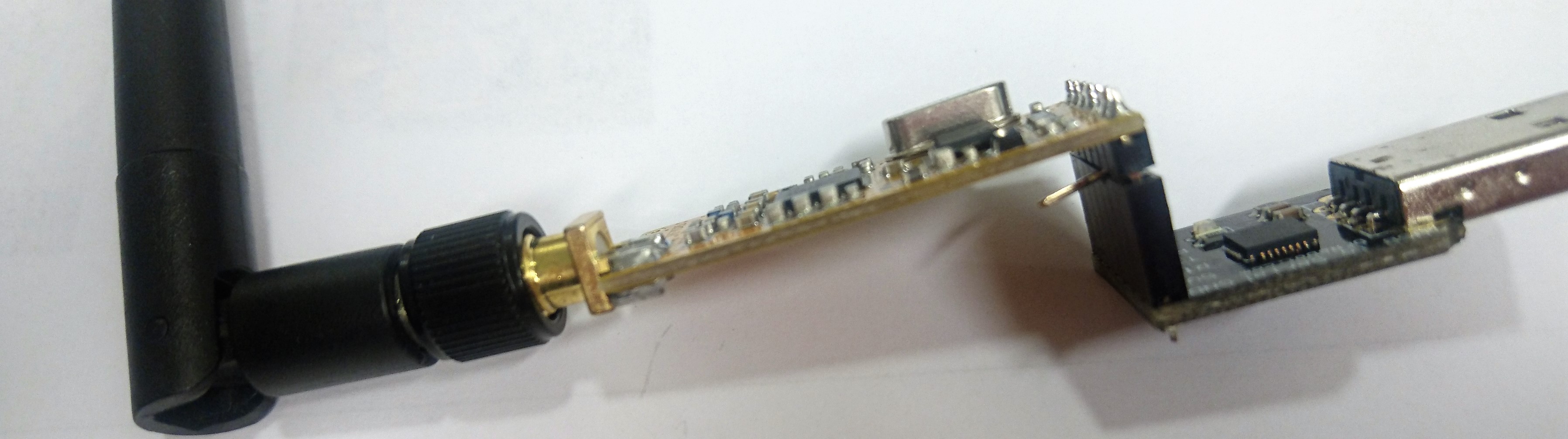
Disconnect the radio module from the USB-to-Serial bridge and lift/bend or isolate the EN pin on the radio module so it isn’t connected to the RTS port of the bridge. Do not remove og destroy the pin, you might need it later. Reconnect to the pc/bridge and open the serial monitor again.