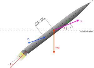
To understand why certain events occur during a rocket launch, one needs to understand which forces act on the rocket, when they occur and why. Refer to figure 1 during this discussion.
In this investigation, we limit the case to three degrees of freedom: horizontal, vertical and pitch (how the rocket is angled compared to the ground, generally called up and down directions). After that, we discuss other important effects.
Center of Gravity (CG)
Two very important points are found on a rocket: center of gravity (CG) and center of pressure (CP). The center of gravity can easily be found by balancing the rocket (as you probably have done with a pencil) on your finger and the center of gravity is the point on the z axis (center axis through the length of the rocket) where the amount of mass on both sides of that point is equal. If you are balancing a body with uniform mass distribution, the center of gravity will be in the middle of the object. The mass distribution function is simple enough, and it can be calculated by hand with an integral.
Center of Pressure (CP)
The Center of pressure is, however, more difficult to comprehend. It is the point along the rocket z axis with the same amount of surface area on both sides. For an object with a simple mathematical shape, it can be found with a simple integral. Generally, it is difficult to calculate and can either be found experimentally—in a wind tunnel—or numerically. Examples of finding the center of pressure of certain rockets are shown in the next section.
Stability
It is important to know where the CG and CP are in absolute measures and relative to each other. The rocket will always rotate around the center of gravity during flight, and gravity act on that singular point. However, the drag and lift forces do act on the center of pressure, and this decide how stable the rocket is.
To understand how stability works on a rocket, let us first consider a wind vane, see figure 2. It is fixed to the ground at a certain point about which it can rotate freely. The wind starts suddenly blowing into the screen from you towards the vane. Which way will the wind vane turn?

The vane will turn so that it points into the wind (the thinnest end rotates towards you, the reader), and the reason is that the wind works on the center of pressure, which can easily be seen to be to our left, behind/left of the rotational point. Since the vane is attached at the rotational point, the front of the arrow will turn into the wind.
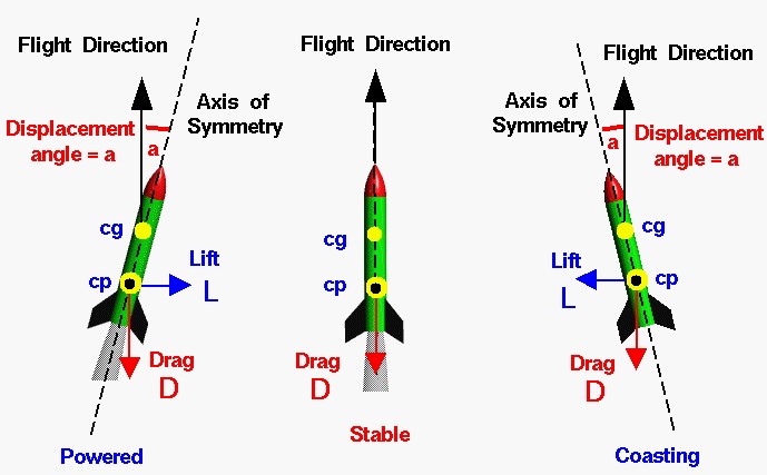
Knowing that the rocket always turns around its center of gravity, it should now be clear why the center of pressure must be behind the center of gravity in order for the rocket to remain stable. Imagine that a rocket is launched straight upwards, and a short burst of wind forces the wind to tilt slightly. After the wind burst relaxes, and given that the rocket is stable, the air pushing on the center of pressure will force it back into the wind again, pictured in figure 3.
For a more visual representation, see this video:
Stability is usually judged by the stability margin (SM), where the distance between the center of gravity and center of pressure is divided by the diameter  of the rocket body,

The general rule when designing a rocket is that the stability margin must be above 1 and should be above 2. The center of gravity is dependent on the burn time. During the launch the center of gravity will move towards the front of the rocket since fuel and oxidizer is in the rear of the rocket. The center of pressure is dependent of the velocity in the fluid medium (the air). This is something that must be taken into account by the software that finds the center of pressure numerically.
Assume the rocket is launched straight upwards, but with non-negligible horizontal winds. The wind is blowing on the center of pressure, and the rocket will then tilt towards the wind. Then the general rule is that the rocket will turn into the wind during its thrust phase, and drift slightly with the wind during the non-thrusting phases of its launch. On large rockets this can be neglected, but on smaller rockets it should be taken into account. This effect diminishes with increasing altitude and decreasing air density.
Let us now separate the forces into two directions, one parallel and one perpendicular to the flight direction. If the angle of attack  is non-zero, this is not the same as parallel and perpendicular to the rocket z-axis. The parallel forces are

where  is the thrust force,
  the thrust mis-alignment angle (see figure 1 above),
  ,
,  ,
,  the distance from the Earth’s center to the rocket,
  the drag force, and
  the mass of the rocket. The forces perpendicular to the direction of travel is

where  is any lift forces, and the remaining variables are as before.
Lift forces are usually small on a rocket, and is always (by definition) perpendicular to the travelling direction. Parallel to the rocket we have then three important forces: thrust from the rocket engine, which is (usually) parallel to the rocket axis ( ), gravitational force, and drag force. Drag force is usually given as

where  is the air density ( ∼1.25 kg/m3 at sea level),
  is the frontal area of the rocket,
  is the dynamic pressure, and
  is the drag coefficient. The drag coefficient is a parameter describing how aerodynamic the rocket is. It varies with the Mach number. Typical values are in the range 0.3–1.3, with a maximum around Mach 1 (the sound barrier).
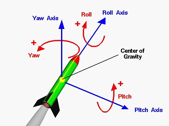
Until now we have only used three degrees of freedom. The other degrees of freedom are the third spatial dimension (‘sideways’ motion), as well as the rotational directions roll and yaw, see figure 4 for the rockets rotation axes.
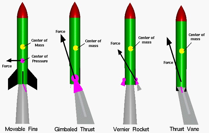
There are two ways to stabilize rockets: active and passive. Active stabilization is using rocket engines (like gimballing the main thrusters or using smaller engines called Vernier thrusters) to control the attitude of the rocket. Active controlling is expensive and complex, but on large rockets it is necessary to use it. See figure 5 for active stabilisation options.
On smaller rockets, as the ones launched at Andøya Space Center for science, one usually does not need to control the rocket attitude after lift-off and the rocket is then stabilized passively using a controlled spin. The spin is usually induced by the fins by aerodynamic forces.
Now that we understand the most important parts of rocket dynamics, we can better appreciate the magnitude of the forces acting on the rockets in this video:
<< Previous page – Content – Next page >>
This article is part of a pre-course program used by Andøya Space Education in Fly a Rocket! and similar programs.