This article gives a brief introduction to soldering, and is aimed at participants without previous soldering knowlegde and/or experience.
A short introductory video about soldering components of the «through hole»-type can be watched here:
Some of the components to be mounted and soldered for the student rocket are surface mounted components, which in general are smaller than the through hole components and therefore require another soldering method. A short video on how to solder surface mounted components can be watched here:
In order to avoid the most common failures when soldering the sensor electronics for the student rocket, we here give a few further comments related to soldering and mounting the sensor electronics:
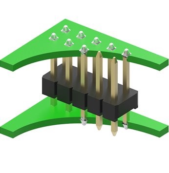
When soldering and mounting small sensor boards like the Teensy LC on to the main sensor board, you’ll need to use distance headers to avoid short circuits. The figure on the right shows an illustration of how to use distance headers. The small sensor board that is going to be placed on top of the main sensor board needs to be oriented so that the components on it are faced up. This is not a general electronics mounting rule, but the layout of all the main sensor boards used in the student rocket have been designed for mounting the small sensor boards «components faced up». So this is the only orientation that will work here.
Radio Module
When soldering the radio module used on some of the sensor boards in the student rocket campaign, there are a few things to be aware of. Like all other components, besides most small surface mounted capacitors and resistors, the orientation is very important. So before starting soldering, be sure that the orientation of the component is right. A square, drawn on the sensor board where the radio module is going to be placed, shows the orientation by indicating where the black chip on the radio module should be placed.
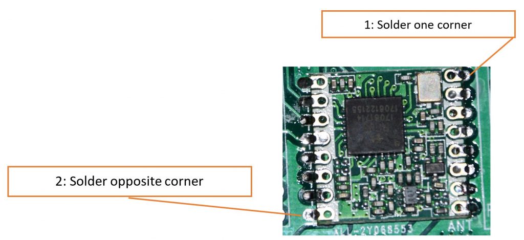
The radio module has several small connector pads that are going to be soldered to the sensor board. The distance between these pads are smaller than the distance between f.ex. distance headers discribed above, and due to the number of pads not to be interconnected, it might require a little more care to place this radio module correct on the sensor board. One of the most important of these connector pads are the one connecting the radio module to the antenna. In the picture this connector pad is the bottom right pad. A suggestion to how to start mounting and soldering this radio module minimising the risk to damage the most important pads, is to start soldering the upper right pad. When this pad is fixed and a visual inspection shows that all the connection pads on the radio module are placed correctly in order to connect only to the sensor board pad that it is supposed to connect to, the next pad to be soldered is the bottom left one. When both these corners are soldered, the rest of the pads can be soldered.
Connectors
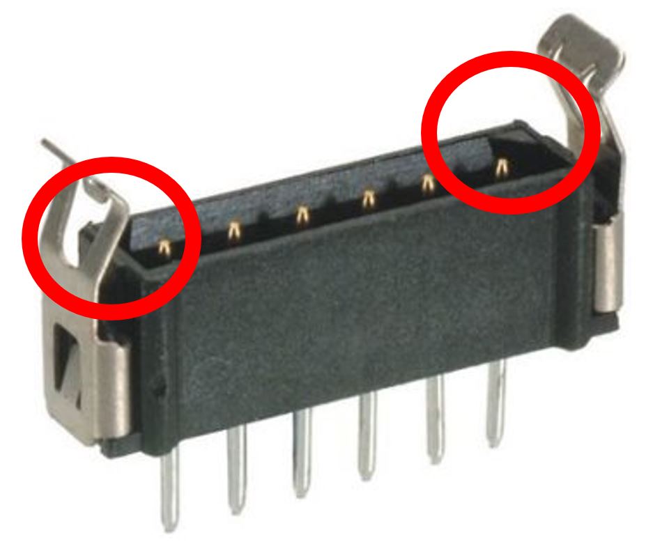
Connectors used to make connections between sensors and the sensor board or between sensor board and the encoder has to be turned the right way when placed on the print board. The reason for this is that the connector will connect to another electronics boards through a multiple-wire cable attached to the connector, and this multi-wire cables other end will again be connected to another connector. The orientation indications on both connector and sensor board are tools to ensure that every single wire in the cable makes the intended connection. As shown in the figure to the right, there are filled corners to help to place the connector in the right orientation.
<< Previous page – Content – Next page >>
This article is part of a pre-course program used by Andøya Space Education in Fly a Rocket! and similar programs.