The student rocket payload consists of a selection of analog and digital sensors. There are eight analog and two digital input ports. All ten ports will be used for the campaign. This article gives a brief introduction to the different sensors that will be used.
An overview of the sensors is given in the following list. Introductions to the sensors will be given in the same order as the appear in the list.
- MMA3202 — accelerometer
- KMZ51 — magnetometer
- MPX5100AP — barometer
- NTCLE100E3 — temperature sensor
- LM35 — linear temperature sensor
- SFH 300 — phototransistor
- LSM9DS1 — inertial measurement unit (IMU)
- Skytraq Venus 638 — GPS module
The first six sensors are the so-called ‘analog sensors’, while the last two are the ‘digital sensors’. As mentioned, all eight analog ports will be used, while there are only six analog sensors listed. In the payload there will actually be two MMA3202 accelerometers, mounted on two different axes, and two LM35 temperature sensors placed in different places inside the payload. The last ‘missing’ sensor is a built-in current sensor connected to the last analog input port. While the NTCLE100E3 is seemingly unused, an array of these sensors will be connected to one of the digital ports, while the GPS and IMU will share the remaining final digital port, thus filling the 10 total input ports.
MMA3202 — Accelerometer
The accelerometer is based on a so-called micro electro-mechanical system (MEMS), where a conducting test mass is suspended between two parallel conducting plates. Hence, due to its construction, the accelerometer measures proper acceleration rather than newtonian acceleration (in other words, it measures the acceleartion due to all forces except gravity). The system forms two separate capacitors with the test mass as a common part. As the test mass is suspended, it will move relative to the two conducting plates whenever the accelerometer is exposed to proper acceleration. If the force needed to move the test mass a certain distance is known—for example by suspending it by a spring with a known spring-constant—the replacement distance can be used to calculate the change in voltage over the capacitor relative to applied force. From Newton’s second law the proper acceleration can then be found as a function of the voltage over the two capacitors.
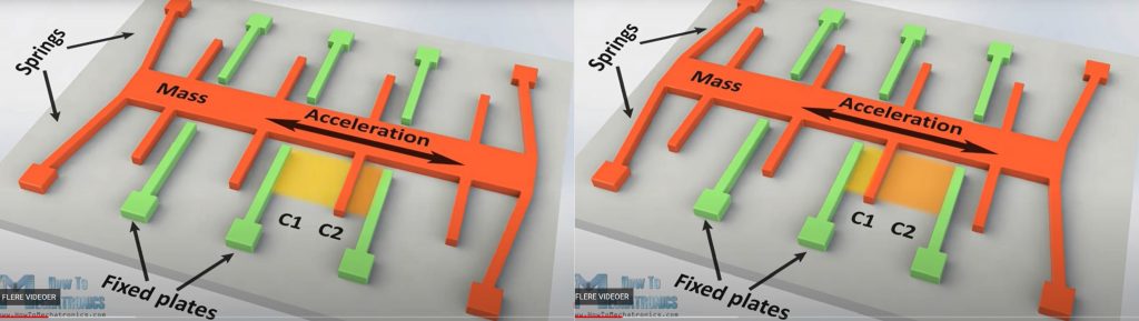
Screen dump courtesy of https://howtomechatronics.com/
KMZ51 — Magnetometer
KMZ51 is a thin film permalloy magnetometer. Permalloy is a nickel-iron magnetic alloy, consisting of approximately 80 % nickel and 20 % iron. One of the properties of this alloy, is its capability of changing its electrical resistivity based on the strength and direction of an external magnetic field. As such the magnetometer can be easily used in an electrical circuit to measure the relative change in a magnetic field, using only Ohm’s law. The permalloy allows for the electrical resistivity to change approximately 5 %. Using a potentiometer and an amplifier, the KMZ51 may then be calibrated to measure small variations in the electrical resistivity, directly translating to small changes in the magnetic field.
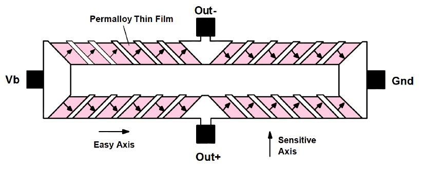
Vb is a bias voltage (taken from Honeywell’s HMC1002 datasheet).
MPX5100AP — Barometer
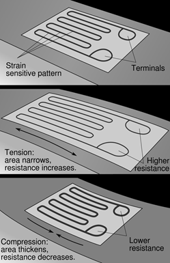
resistance varies in a strain gauge
To measure the pressure the MPX5100AP uses a piezoresistive strain gauge in combination with other non-disclosed micromachining techniques. A piezoresistive strain gauge will change its electrical resistivity based on the amount of strain applied. Usually, as in the MPX5100AP, the strain gauge consists of a thin film with a conducting material placed on it in a zig-zag pattern. When the film is bent due to strain, the conducting leads will either be compressed and shortened, which decreases resistivity, or stretched and narrowed, which will increase resistivity. As explained for the magnetometer, when the sensor changes its electrical resistance it is easy to calculate the change in pressure using Ohm’s law
NTCLE100E3 — Temperature sensor
The NTCLE100E3 is a series of thermistors. For the payload a series of 10 kΩ thermistors is used to form an array of temperature sensors. NTC is an abbreviation of ‘negative temperature coefficient’, meaning the electrical resistance of the sensor changes negatively with respect to the temperature. I.e. if the temperature increases, the resistivity of the sensor decreases. A 10 kΩ thermistor will have a resistance of 10 kΩ at 25 °C, with a nonlinear change in resistivity based on the temperature. The change in resistivity can be calculated using the Steinhart–Hart equation, using coefficients given in the datasheet of the thermistor. This equation calculates the temperature based on the thermistor and a reference resistor, connected as a voltage divider.
LM35 — Linear temperature sensor
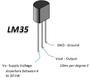
Image courtesy of Xyntax pro solution.
Two LM35 integrated circuit temperature sensors will be placed inside the payload to measure the battery and internal temperatures. In contrast to the passive NTC thermistor, the LM35 is an active sensor, requiring an input voltage to function. The sensor itself has three pins, a voltage input, a ground pin, and a voltage output. The voltage output scales directly to degrees Celsius with a 10 mV/°C increment, meaning there is no need for complex and confusing equations as was the case with the NTC. Furthermore, the LM35 is scaled to measure 0–100 °C with an output voltage between 0–1 V. As the payload system works on 5 V, the output voltage of the LM35 has to be scaled using an operational amplifier.
SFH 300 — Phototransistor
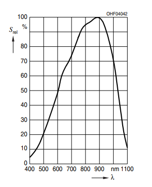
Image taken from the datasheet.
A phototransistor consists of two leads connected to a semiconducting material. For the SFH 300 the semiconductor is silicon, which is then divided into two parts. One part is the P-type anode, which is doped to contain more holes than electrons. The other part is the N-type cathode, which must be oppositely doped with respect to the anode, so it contains more electrons than holes. Since silicon is only a semiconductor, no charge can move from the anode to the cathode without any external influence. In a phototransistor this external influence is the light shining on the sensor. When light of sufficient energy hits one of the electrons in the N-type silicon, the electron is excited and gains enough energy to move over to the P-type silicon. The number of electrons transferring from the cathode to the anode determines the current through the phototransistor, which in turn can be translated to a voltage. The SFH300 has a spectral range of approximately 450 to 1100 nm, meaning light within these wavelengths has the correct energy to excite electrons in the cathode.
LSM9DS1 — Inertial measurement unit (IMU)
The inertial measurement unit consists of 9 sensors, measuring acceleration, angular velocity, and magnetic field strength, all along three axes. It is a digital sensor, which can output data on either an I2C serial bus or an SPI serial standard interface. One advantage of using a digital sensor is the ability to control the sensitivity through software. The LSM9DS1 can be programmed to measure (proper) accelerations between ±(2–16)g, magnetic field strengths between ±(2–16) G and angular velocities between ±(245–2000) dps. Using the accelerometer as an example, it will measure proper accelerations in the range from –2g to 2g if programmed to measure ±2g.
The accelerometer and angular velocity sensors are all MEMS-type sensors. As such the accelerometers will function in the same manner as the previously explained MMA3202 accelerometer. For the angular velocity sensors, a system where a vibrating conducting ring connects to spokes on an outer, stationary ring based on the vibrational modes. The vibrational modes are determined by the angular velocity the system is subjected to, making it possible to measure the angular velocity through the voltage in the circuit. Lastly, the magnetometer technology is not disclosed. However, it is likely to be one of two kinds of magnetometers: a Hall sensor or a magnetoresistive material. A Hall sensor uses the Hall effect to determine the magnetic field strength, while a magnetoresistive material—much like the thermistor—changes its electrical resistivity based on the applied magnetic field.
Skytraq Venus 638 — GPS Module
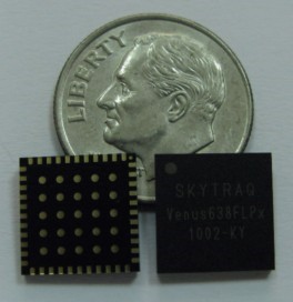
Image courtesy of SkyTraq Technology, Inc.
Originally built at a cost of over $10 billion mainly for military navigation, GPS has rapidly transformed itself into a thriving commercial industry. The system is based on an array of 24 satellites orbiting the earth, each carrying a precise atomic clock. Using a hand-held GPS receiver which detects radio emissions from any of the satellites which happen to be overhead, users of even moderately priced devices can determine latitude, longitude and altitude to an accuracy which can currently reach 15 meters, and local time to 50 billionths of a second. Apart from the obvious military uses, GPS is finding applications in airplane navigation, oil exploration, wilderness recreation, bridge construction, sailing, and interstate trucking, to name just a few.
To determine its location, a GPS receiver uses the time at which the individual signals from each satellite was emitted—as determined by the atomic clock on-board the satellite and encoded into the signal—together with the speed of light, to calculate the distance between itself and the satellites it communicated with. The orbit of each satellite is known accurately. Given enough satellites, it is a simple geometric problem to compute the receiver’s precise location, both in space and time. To achieve a navigation accuracy of 15 meters, time throughout the GPS system must be known to an accuracy of 50 nanoseconds, which simply corresponds to the time required for light to travel 15 meters.
The Skytraq Venus 638 GPS is a single-chip module, operating at a low power consumption, making it ideal for low-power systems such as the rocket payload. It has an update rate of 20 Hz, giving 20 GPS tracking points per second. As with any other GPS receiver, it needs to locate enough satellites before being operative. Since the GPS is a digital sensor, it can be programmed to output the desired data in a variety of formats.
<< Previous page – Content – Next page >>
This article is part of a pre-course program used by Andøya Space Education in Fly a Rocket! and similar programs.